Die Design
Die Casting Die development is an important activity bridging product design and manufacturing activities. Die development broadly compromises of three tasks: design, manufacturing and tryouts. Die design includes design of core and cavity block, gating system (gate-runner, runners, overflows and vents), cooling system and mechanical system (ejection system, guiding system and die housings)
The shape of a die cavity must correspond to the dimensions of the part to be cast, plus drafter taper, to facilitate ejection, plus an allowance for shrinkage. For close tolerance castings, allowance must also be made for thermal expansion of the die cavity. The placement of the cavity in the die block is governed by
1.
Parting
line requirements
2.
Requirements
for moving cores and slides.
3.
Location
of non-critical area in the casting for gating
4. The need for positioning the gate so that cores or other members does not obstruct the initial flow of metal.
Draft
All casting
walls that are perpendicular to the parting line require draft or taper, so
that the casting can be withdrawn without sticking or scoring. The amount of
draft varies with the casting metal and with height of the casting walls. The
draft on cavity side is half that required for inside walls. The amount of
draft affects the amount of lubrication required, the speed of the casting
cycle and the precision of the casting.
Parting Line
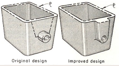
Parting-line shape and location have a considerable effect on the economy and effectiveness of any die casting operation. A straight parting line, permitting flat die surfaces is preferred. Flat surfaces on the die halves are more economical to machine than contoured surfaces. Moreover, with flat surfaces it is easier to maintain a seal between the two die halves. The parting line should be in an area on the casting, where the flash and gate will be easy to remove and where any marks resulting from trimming will have the least effect on function, on surface finish and appearance. The circular boss on the sidewall of a die cast housing required a recessed parting line as the use of slide. Either approach resulted in an expensive and complicated die. Extending boss (Improved design) permitted the use of straight parting line, thus simplifying die design and lowering die cost.
Shrinkage Allowances
In
establishing dimensions for cavities and cores, an allowance must be added to
the dimensions specified for the part to be cast, for shrinkage of the casting
metal. The shrinkage allowances normally used are
1.
0.5%
for zinc alloys,
2.
0.6%
for aluminum alloys
3. 0.7% for magnesium alloys
Parting Line
The circular boss on the sidewall of die
cast housing required a recessed parting line as shown in Fig. or the use of
slide. Either approach resulted in an expensive and complicated die. Extending
boss (Improved design) permitted the use of straight parting line, thus
simplifying die design and lowering die cost.
 |
| Parting_Line |
Use of Cores
Shows
the use of a three-element core in die casting of a cylindrical part with an
undercut produced by internal bosses around side holes. The core pins were
stationary in the ejector and cover halves of the die. Core element A was an
integral part of the slide and core elements
Ejection Systems
Gating System
The gating system
includes the entire die elements needed to feed liquid metal to the die
castings, namely runners, gate inlet or fore gates, gates, vents overflow and
chills. The gating system is a preponderant factor in the production of
acceptable die castings. Properly designed, it:
- Determines whether a stable flow of liquid metal is supplied to the casting during the fling period.
- Provides for entrapment of oxides, lubricants and other Impurities in overflows outside the body of the casting.
- Controls metal turbulence and impingement throughout the Filling period.
- Provides the necessary feed metal to reduce shrinkage Influences die life.
Gate thickness in mm
Gating Formula
Calculation of Casting Area & Locking Force
 |
| Calculation_of_Casting_Area_&_Locking_Force |
Runner Design
 |
| Runner_Design |
Vents
Overflows
Cooling
Materials Used for Die Parts
 |
| Materials_Used_for_Die_Parts. |
Materials & hardness Chart
 |
| Materials_&_hardness_Chart |


For more information, please comment here. ConversionConversion EmoticonEmoticon